This particular steady was designed for my Twister -FU200 lathe, but it can easily be adapted for lathes of similar centre height, and (with a bit of work) even for lathes with other centre heights. During the design there were a few things I wanted to accomplish:
- Maximum size range (here from about 50mm to over 320mm)
- Good stability
- Can be made by myself
- Affordable components
Here’s the design I came up with:
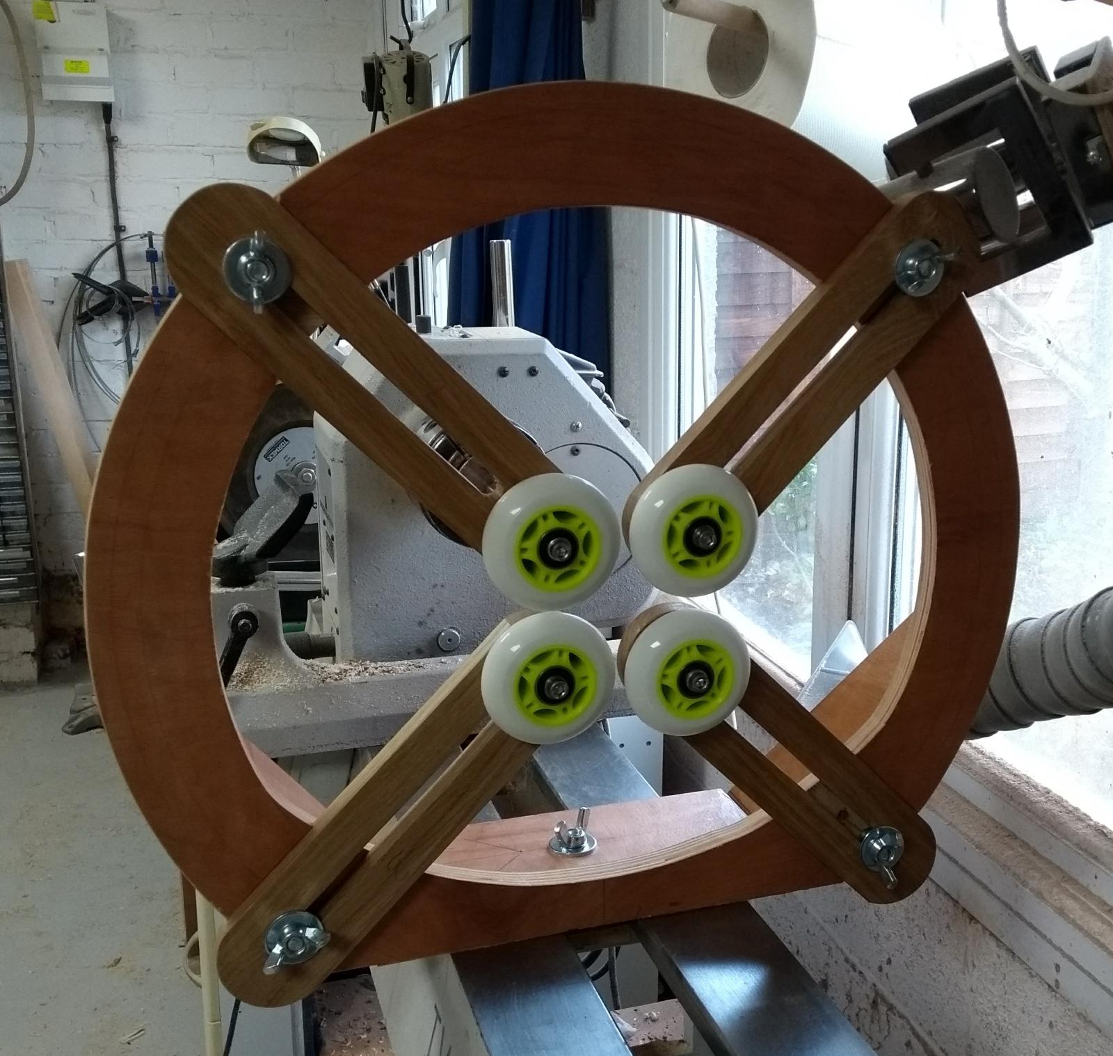
For the wheels I decided to use inline skater wheels, and after some discussion with a specialist skating company I settled on the ones you can see in the picture below. They are 72mm diameter and are made from a non-marking polyurethane product, which behaves similar to a medium hard rubber. Cost is about £20 (which includes the 4 wheels and 8 suitable ball bearings, 2 per wheel). These wheels need to have axles going through the wheel and the support arm. I will make these axles from 12mm round aluminium bar. Other materials are permissible, and as long as you don’t put huge pressure on the wheels, you could even consider making them from some hard wood, oak or laburnum or harder. It’s worth remembering that in this case the axles don’t actually move, and therefore wear and tear isn’t really too much of a problem.
So here are (most of) the components making up the steady:

What isn’t shown in the picture are various pieces of standard hardware, i.e. bolts, washers, nuts, etc. Please note the diagonal lines on the main support frame.
As you can see, the main body of the steady will be made mostly from high grade 18mm plywood. I would not use the standard stuff you can get from your average DIY store, that just does not have the same quality. You really need the top grade material from a proper timber merchant. The support arms are made from oak, but could be made from a variety of materials such as plywood, ash, maple. Pretty much any hardwood will do, as long as it is quite stiff (you’re not going to have much success with pine).
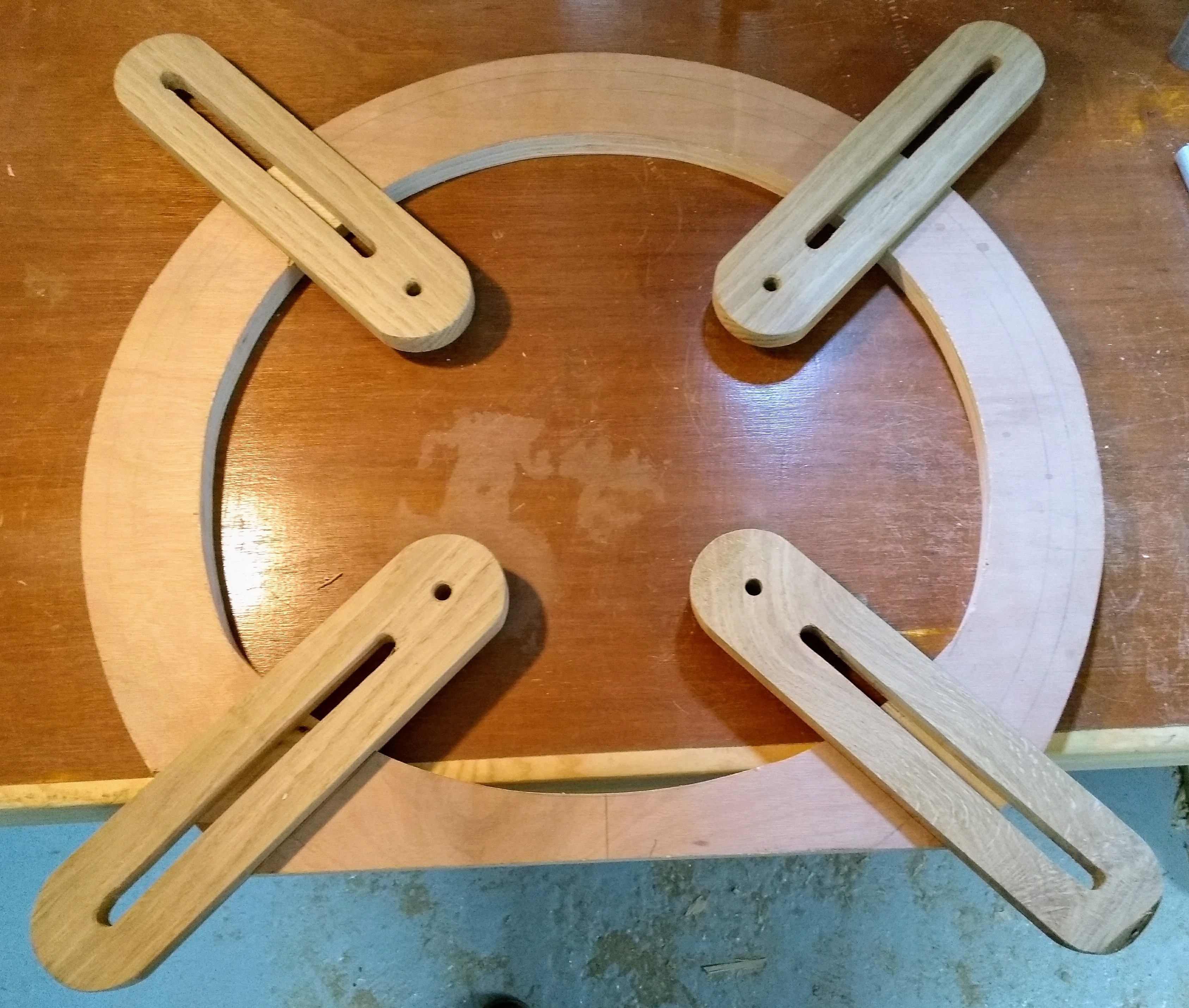
Support arms cut out, drilled and marked out
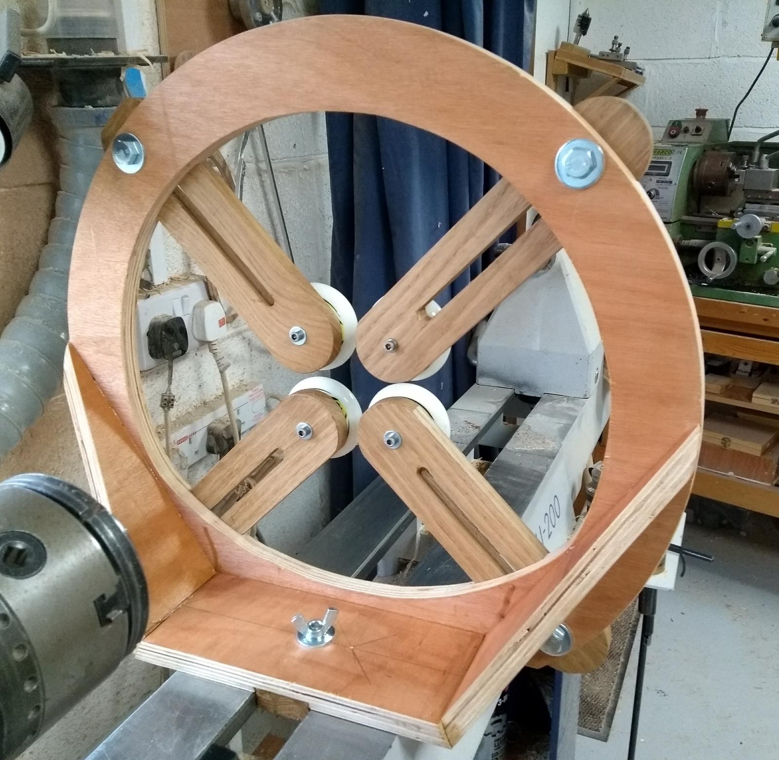
About the design itself: the opening is not entirely circular. In order to improve stability, the bottom half is dominated by an arc of 245mm radius with the centre offset by 75mm towards the top. This does not impede on the maximum diameter that can be turned, which itself is actually determined by the maximum outward position of the support arms. It is for this reason that the dashed arc indicating the locations of the holes for the support arm locking bolts is very much towards the outer rim, thereby maximising the possible work piece diameter.
The drawing also shows that the foot plate is angled on both sides (about 62 degrees), which matches the angle on the struts going up towards the centre height on either side of the support ring. These struts are definitely needed to prevent movement of the arms. Both struts and the foot plate will be glued together, with additional hardwood dowels in all joints (screwing into end grain is not a good idea when vibrations are present).
Support arms machined, planed on both sides, chamfered and ready.
In the centre of the foot plate is another small piece of oak dimensioned such that it is a precise fit for the gap between the sides of my lathe bed. This will be glued together and a whole in the centre will allow me to drive a long screw through it, with another piece of oak at the end so that the entire steady can be bolted onto the lathe bed.
The support arms have 9mm holes at one end (for the axles holding the wheels) and a 10mm slot running along the rest of the arm so that the distance from centre can be adjusted. No particular precision is required when these slots are cut. However, the width of these arms should be controlled with some care. If possible, all 4 should be precisely the same, that makes it easier to make and fit the slots in the main support frame.
The foot plate and both support struts have angled sides, with a 62 degree angle on both. This has to be quite precise to support the best possible glue joint between these components.
Support frame with recesses cut and fitted
The support frame now needs to receive 4 recesses (slots? dados?) in which the support arms will glide forward and backward. The depth of these recesses is a compromise between support for the arms and stability of the frame. In my case I chose about 5mm, and they were cut with the radial arm saw (however, a nice tenon saw and a sharp chisel will do the trick, too).
Next steps are the glue-up of struts and foot plate, and the turning of the axles. Will be continued as I make progress and take more pictures.
Feel free to make your own from a download of the above drawing. If you want proper design drawings, email me through the comments or the contact form (there will be a charge for them).
Considerations for other makers:
- I made my axles from 12mm aluminium rod, simply because that’s what I had. They can be made from many other materials, including proper hardwoods. These axles don’t actually move themselves, they just hold the wheel bearings on one side and the support arm on the other. In consequence they could be made from 8mm bolts, too. In this case reduce the holes drilled into the support arm to 8mm (or just under) and make sure your washers are small enough to not touch the outer casing of the ball bearings (the inner casings are static anyway), so that you can fit a wash under the bolt head, between arm and wheel and on the outside of the wheel, without introducing any unwanted friction.
- If you make your axles from hardwood, you probably should follow a similar design to mine, with 2 (threaded) holes on either end, so that you can use screws with washers to prevent unwanted movement.
- Similarly, the slots in the support arms are 10mm, because I had suitable 10mm bolts. There is nothing preventing you from using 8mm or 12mm bolts (or any other size). Do make sure to use large washers to distribute the pressure when locking the arms in place.
- I have used wingnuts on the support arm bolts, but these could also be standard nuts (but then you need to use a spanner).
- The design will support wheels of 65mm diameter and up. The smaller, the better. If you want to use smaller wheels still, you can do so by
- Reducing the width of the arms from 60mm to a smaller size, ideally slightly smaller than the wheels, and
- Moving the axle hole closer to the rim (less than half the diameter of the wheels), and
- Making the arms longer, so that you can move closer to the centre, thereby allowing a smaller minimum diameter of work piece.
- The steady was designed for the Twister FU-200, with a centre height of 200 mm and a bed width of 180 mm with a 45mm gap. Changes to bed width have almost no consequence, changes in the gap width only really affect the size of the guidance block in the centre. A change of centre height can be achieved, but essentially requires complete re-dimensioning of all components. A change in bed design can be done. but requires a re-design of the foot plate, guidance block and clamp block. How this would work for lathes with a bed made from 2 round steel bars, I am not sure.
Any questions, just contact me. If you want one, but don’t have the time/machines/etc, I can make one for you (at a cost).
Part II
Here’s a picture of the glue-up of the frame:
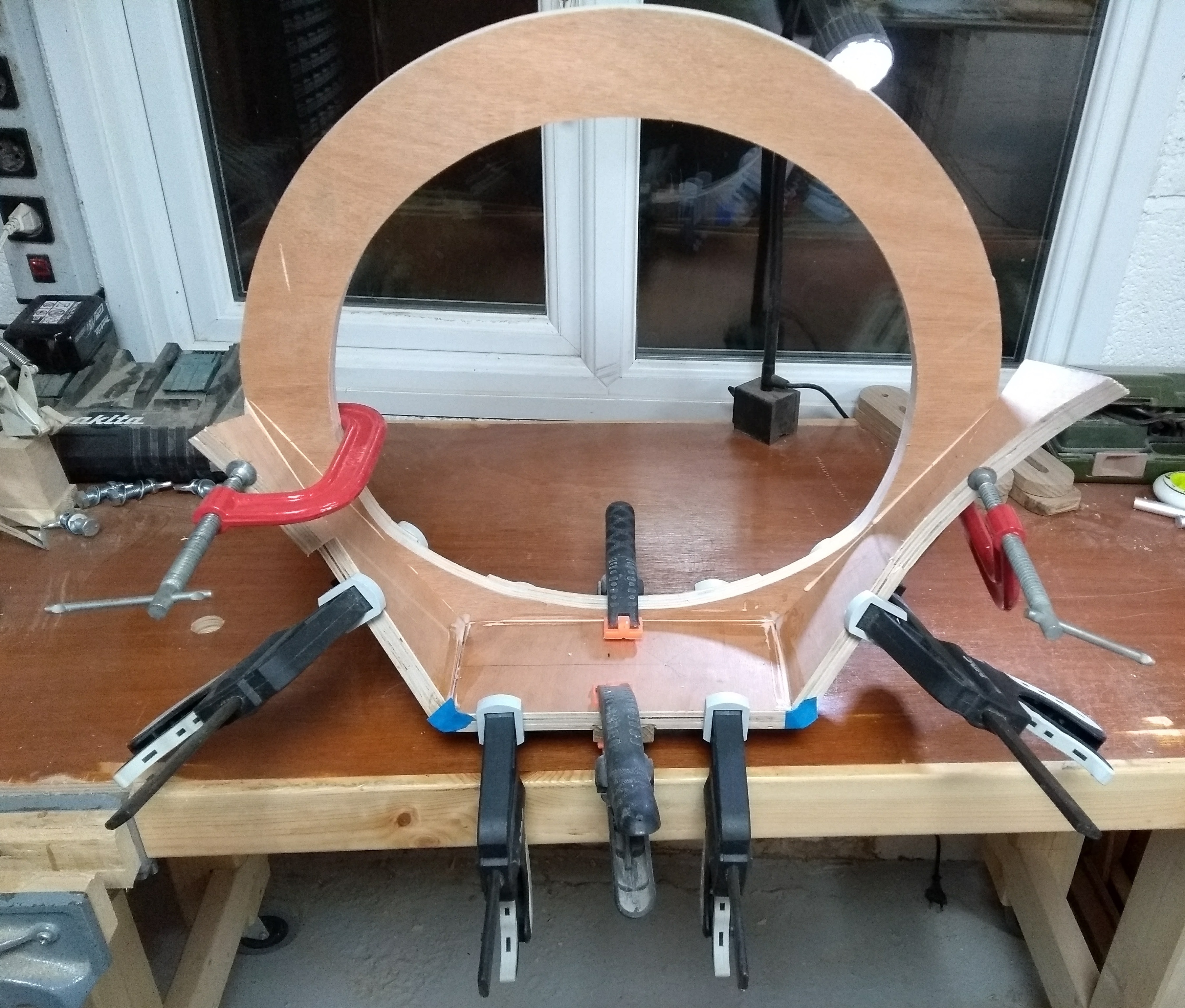 All the joints were reinforced with 8mm dowels, although you could also use screws (with a bit of pre-drilling to prevent the plywood from splitting). The glue is Titebond III, a PU glue that dries up with a brown colour and expands slightly during drying. I provides an excellent bond and is usually stronger than the wood itself.
When assembling the frame, it is quite important to get a decent fit between all the pieces, as this will improve overall stability.
Once the frame is glued, holes need to be drilled for the bolts holding the arms, and also a hole in the base to hold the bolt that clamps the stead to the lathe bed. After that, the 4 axles for the rollers were made from a 12mm aluminium rod. I don’t have a drawing for that at the moment, essentially the rod is reduced to 8mm diameter for 24mm length to fit the bearings in the rollers, and reduced to 10mm for 16mm length to fit a 10mm hole in the arms, with a centre bulge of around 2mm width of full rod thickness. This centre bulge separates the roller from the arm, and thereby allows free movement. All these dimensions have to be quite precise to prevent unwanted wobbling of the axles. In order to fasten it all together, I drilled a hole all the way through of 4mm diameter, and then cut M5 threads into it, so that the rollers and arms can be held in place with M5 screws with big washers.
Here’s the whole unit completely assembled:
And from the back:
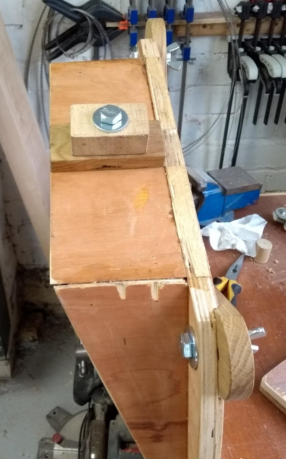
The foot with the locking bolt:
 I treated all of the wooden surfaces with a single coat of sanding sealer, this is mostly to prevent any possibility of damage in the event of contact with water, and it also makes sure that the wood will not get grubby from handling. Incidentally, the arms also benefit from the sanding sealer, as with a little bit of slight sanding at 400grit, the surface becomes very smooth.
As you can see there’s a block of oak glued into the the foot of the frame. This block is precision cut and sanded to be a perfect fit for thee gap in the bed. In addition, I glued a thin strip of oak onto the underside of face of the frame. This strip was then planed and sanded by hand until the face of the frame was perfectly at a 90 degree angle to the bed.
The locking block is another piece of oak, which will fit into the gap, and is then rotated by 90 degrees before the wing nut on top (see picture above) is tightened.
I haven’t used the steady yet, but so far my tests have shown decent frame rigidity. I’ll update this post once I have some feedback from real use.
UPDATE:
I have now used this steady on many occasions, and it is now on its second set of wheels and bearings. It has proven to be invaluable for many jobs, especially when hollowing deep vases or boring long big holes into wooden clubs (so they can be fitted with lead sash weights to make them heavier).
If anybody would like to get a set of drawings, fill in the contact form on this site and I’ll send them over FOC.